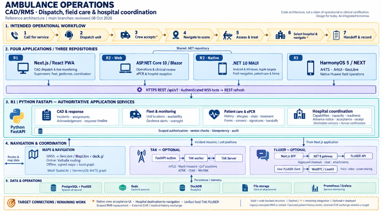
Ambulance platform architecture
Reference diagrams for web command apps, native field operations, shared FastAPI services, and the data layer that connects dispatch through clinical handoff.
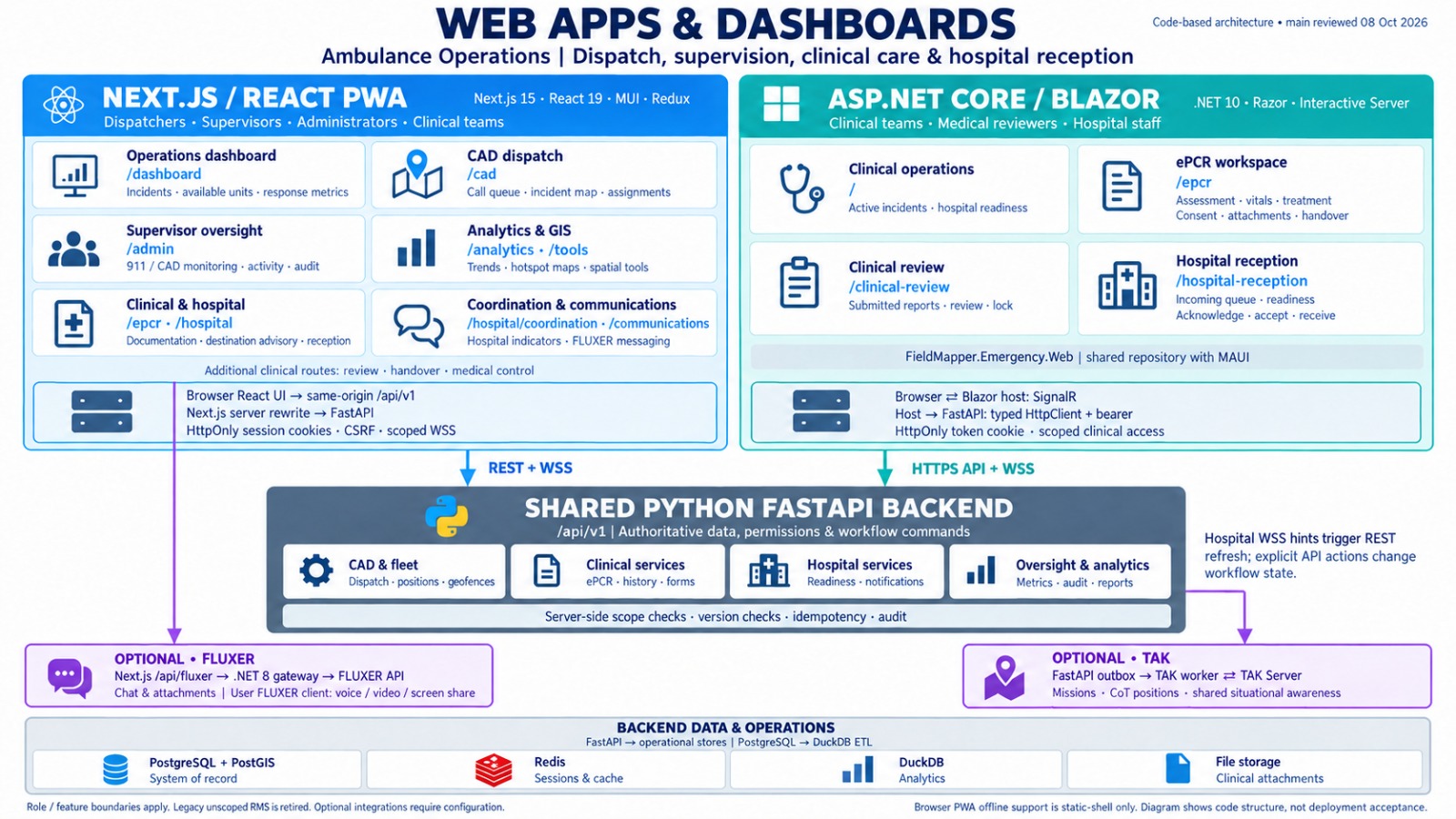
Web apps & dashboards
Command and clinical web stack for dispatchers, supervisors, administrators, and hospital teams. Next.js / React PWA and ASP.NET Core / Blazor front ends share one Python FastAPI backend for CAD, ePCR, hospital reception, analytics, and optional Fluxer / TAK integrations.
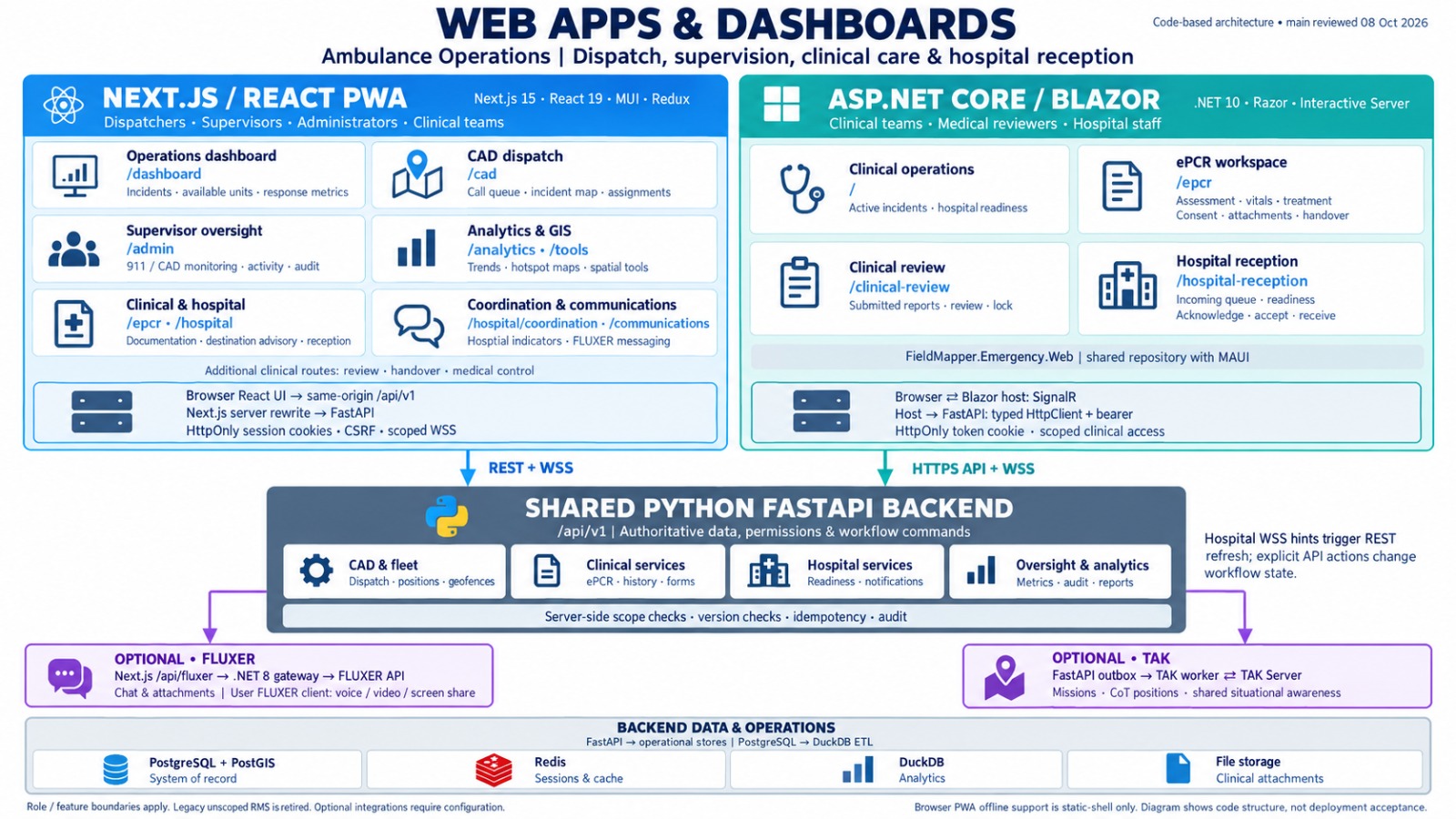
Shared services & data layer
How the web applications connect to authoritative /api/v1 services, optional chat and TAK workers, and the operational data plane — PostgreSQL + PostGIS, Redis, DuckDB analytics, and clinical file storage.
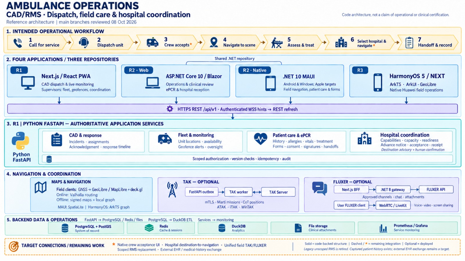
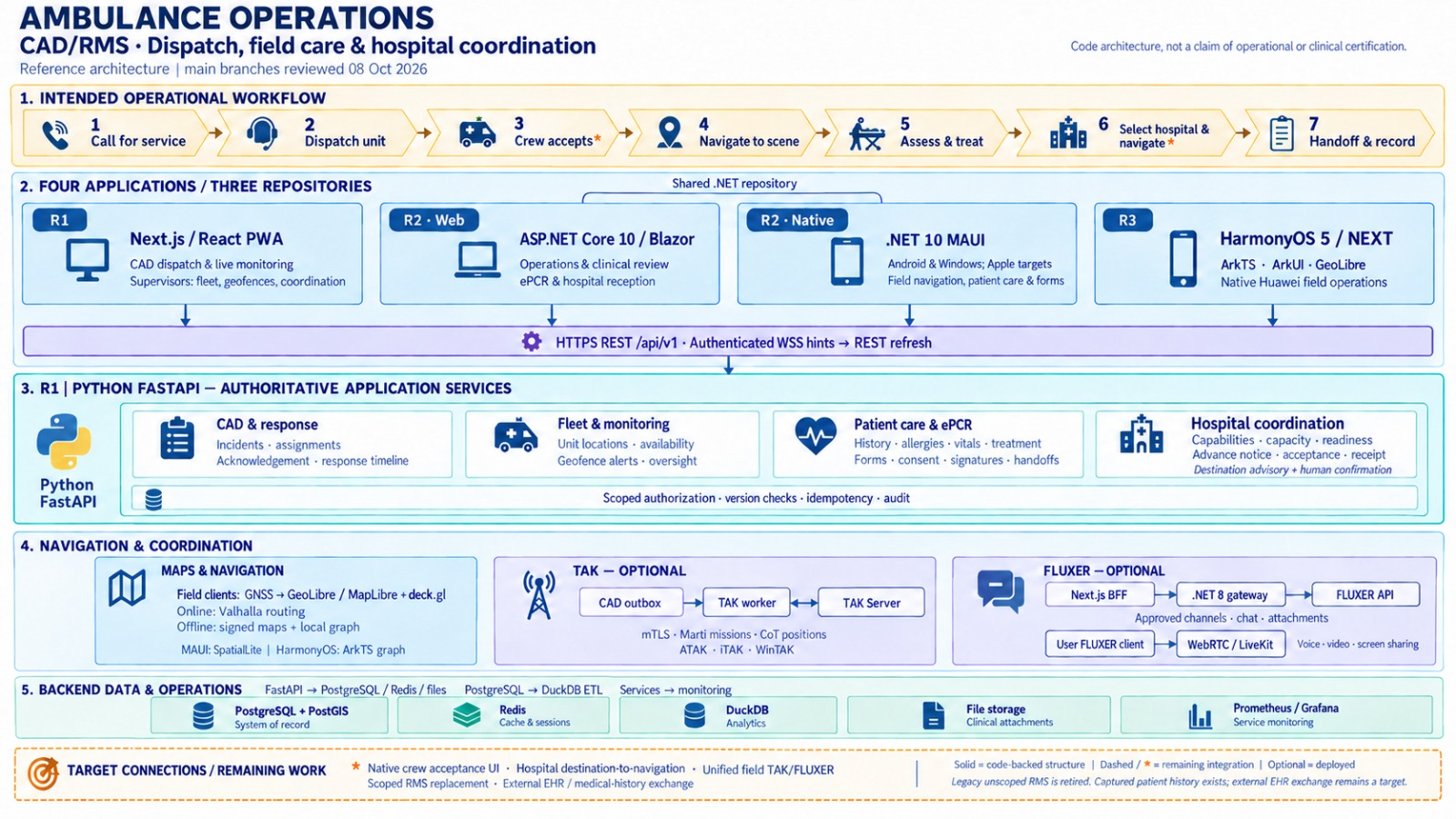
CAD / RMS end-to-end architecture
Full Ambulance Operations reference from call-for-service through hospital handoff. Shows the intended operational workflow, four client applications across three repositories, FastAPI service modules, maps/navigation, and backend data & monitoring.
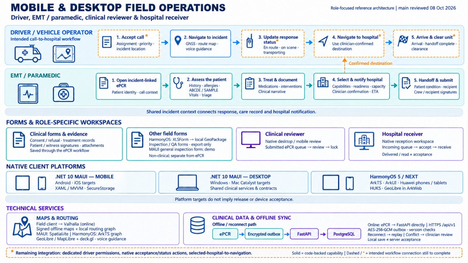
Mobile & desktop field operations
Driver and EMT / paramedic call-to-hospital workflows on native clients. Covers incident-linked ePCR, hospital selection, .NET MAUI and HarmonyOS apps, offline clinical sync, and maps & routing used in the field.
Applications, APIs & FastAPI services
How CAD/RMS clients (Next.js, Blazor, MAUI, HarmonyOS) talk to the authoritative FastAPI layer for CAD & response, fleet monitoring, patient care / ePCR, hospital coordination, and security auditing.
Navigation, coordination & operations data
Maps and routing (online and offline), optional TAK situational awareness, Fluxer communications, and the data/operations stack that keeps dispatch, clinical, and hospital context in one system of record.